1 Introduction
The liquid level transmitter is a commonly used transmitter for domestic liquid level measurement. It has a simple structure and is easy to install. It is very accurate for the liquid level measurement, so it is trusted by many manufacturers. Today, we will talk about the liquid level transmission. Those maintenance methods and maintenance procedures during use.
Second, maintenance :
1. When the liquid level transmitter freezes in winter, the transmitter installed outside must take anti-freezing measures to prevent the liquid in the pressure inlet from expanding due to the volume of the ice, leading to damage to the sensor. 2. When wiring, pass the cable through the waterproof connector (accessory) or the winding tube and tighten the sealing nut to prevent rainwater from leaking into the transmitter housing through the cable. 3. When measuring the pressure of the gas, the pressure port should be opened at the top of the process pipe, and the flange level transmitter should also be installed in the upper part of the process pipe to allow the deposited liquid to be quickly injected into the process pipe. 4. When measuring the steam or other high temperature medium of the liquid level transmitter , it is necessary to add a condenser such as a buffer tube (coil tube), and the operating temperature of the transmitter should not exceed the limit. 5. Double flange liquid level transmitter should pay attention to the pressure guiding tube of the sensor to be installed in a place with small temperature fluctuation. 6. When measuring the liquid pressure, the installation position of the flange liquid level transmitter should avoid the impact of liquid (that is, water). Hammer phenomenon), in order to avoid sensor over-voltage damage. 7. When measuring the liquid pressure, the double-flange liquid level transmitter should be opened on the side of the process pipe to avoid sedimentation. 8. Prevent the flange liquid transmitter from coming into contact with corrosive or overheated media, and prevent the dross from depositing in the conduit;
Third, the fault problem steps are as follows: (sorting in no particular order)
1. Check the two transmitters on the site first to check whether the transmitter's range has a selection or manufacturing error. 2. Verify the zero position of the two transmitters to see if there is a pressure relief problem. (The result is zero normal) 3. Please confirm that the two transmitters in the field must be consistent with the on-site installation method when adjusting. Then, under this precondition, please check the transmitter's capsule for foreign matter or media crystallization, because if there is foreign matter or crystallization, the pressure will change, and the final 4-20 mA output signal will become larger. 4, the above 3 points have been checked, no problem, the result of the final inspection of zui is a small detail, it is not any of the above possible situations, that is, there is a ball valve in the installation part, there is a rubber pad inside, and the result is not taken down. Negative pressure is generated, which affects pressure changes and output. Of course, this kind of detail is impossible to think of. Only one factor can be found and checked. However, if you do not check, check, and separately according to the theory, it is easy to judge the error, resulting in a normal transmitter but to return to the factory for repair, it is a thankless thing.
The domestic current situation of the die-casting mould
Die Casting Mould industry has developed rapidly in our country, the total output growth significantly, domestic die casting mold production after the United States, has become the second in the world, become the veritable die-casting superpower. It can have such achievement because of our country with unique broad market advantages and relatively cheap labor force. Depend on very obvious price in the international trade market, we produced the die casting mould which occupies a bigger superiority, according to the situation, in the future Chinese die casting industry development prospects are very broad.
The designing of die
casting tooling
1, According to the materials, shape and precision product, analyze technology,
decide of the process.
2, Confirm the location of product in the mold cavity. Analyze parting surface,
overflow system and the gating system.
3, Design the various activities of the core are assembled and fixed method.
4, Design the core-pulling distance and force.
5, Design the ejection device.
6, Confirm the die casting machine, design the mould base and the cooling
system.
7, Checking the mould size and die casting machine, drawing the process
flowchart and component of die casting mold.
8, Design is complete.
Die-casting mould making flowchart

Aluminum injection mould material and materials and its properties
Material of aluminum die casting mould: H13, ASSAB DIEVAR, SKD6;
Mould base: #45 steel, standard mould base (LKM);
Hardness after treatment: RHC 48~52;
Standard Configuration: Cooling system;
Tolerance: 0.1mm;
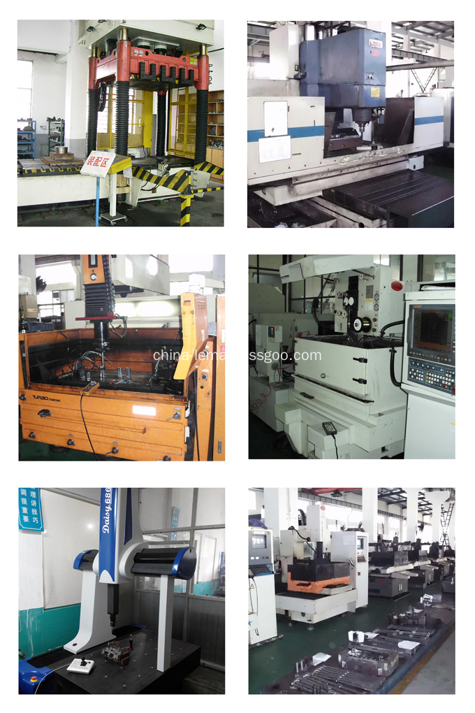
Machining equipment: CNC gantry milling machine, middle-speed WEDM machine, slow-feeding EDM, die spotting machine;
Mould life: 50000 shots ~ 100000 shots;
Lead time of die casting mould: 40 days-60 days.
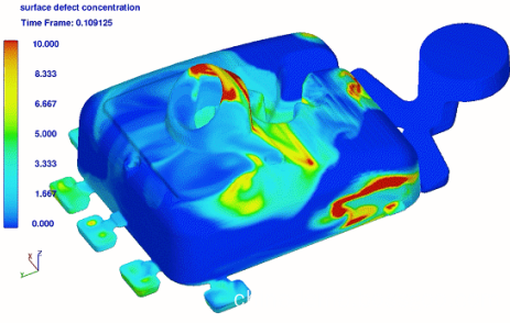
What is the Moldflow analysis, this conception derived fromtaiwan. it's a precess through the computer for injection molding simulation by data simulate software, and get data result. Then assess the feasibilty of the mold program through these results to perfect mold and production designation.The common software for plastic mold such as moldflow, moldex 3D and so on. And the common software for Aluminum Die Casting Parts such as PROCAST, FLOW 3D and so on.

The conventional materials of die casting core, insert, slider

Production of die casting mould and QC control

Die Casting Mould
Aluminum Die Casting Mould, Zinc Die Casting Mould, Die Casting Mould, Die Cast Mold
NINGBO BEILUN LEMA MACHINERY TECHNOLOGY CO.,LTD , http://www.china-lema.com